Get in touch with Suzhou Simitch Machinery Co., Ltd Company

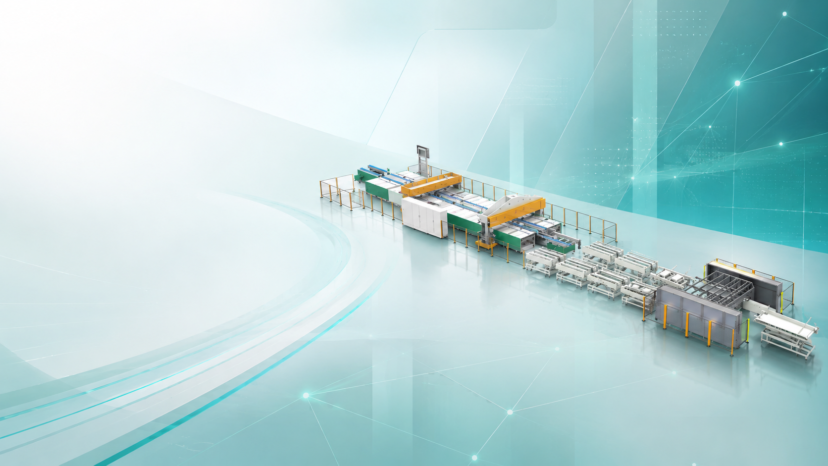
Simitch sheet-metal joining equipment
Automated Riveting Equipment for Elevator and Rail Transit
Simitch plans automated riveting around your part, joint access, material stack, fixture, production flow and quality record. Possible outcomes include a dedicated riveting station, a robotic riveting system or a connected assembly line.
Application first. Machine second.
We do not select an automatic riveting machine from a generic force or cycle-time table. Drawings, samples, access direction, fastener choice and acceptance needs set the engineering boundary.
01
Since 2006
Sheet-metal connection machinery experience
02
3 paths
Dedicated station, robot cell or integrated line
03
1 matrix
Part–Joint–Process–Quality selection logic
Automate Large Sheet-Metal Riveting Without Losing Process Visibility
Large elevator and rail parts create a familiar tension: the assembly must move through production, yet every fixture, rivet location and access path can become a source of delay or rework. Simitch builds the equipment proposal around that physical sequence instead of treating the rivet tool as an isolated purchase.
Technical Boundary
A peer-reviewed self-piercing riveting overview shows why monitoring and automation still need joint-specific validation. It is not evidence of Simitch performance or a buyer’s result.
STATEMENT
The Honest Version
Choosing a fully automatic riveting machine is not always the right call. Dedicated stations or operator-assisted cells may give better access, simpler recovery and a clearer investment case when part variation is high.
FLOW / 01
Part flow
Define how operators or material handling load and unload the part, where it is referenced, and which features must remain protected.
FLOW / 02
Joining flow
Map rivet placement, tool approach, die support, feed path and recovery steps prior to fixing motion hardware.
FLOW / 03
Information flow
Agree which settings, operating states, alarms and results the control system must present or retain.
CHALLENGES
The problem is usually at the interfaces
- Late fixture changes turn a clean equipment quote into a costly integration problem.
- Even a feed path that works during a short demonstration may still need replenishment, jam access and recovery logic.
- Part variation can move a nominal rivet point outside the tool or die access window.
- Quality teams may need traceability that a stand-alone riveting machine never had to provide.
EVALUATION
What Simitch reviews
- Part drawings, reference datums and allowable clamping areas
- Joint schedule, rivet types and access from one side or both sides
- Current riveting processes and the steps you want to automate
- Production requirements, changeover pattern and operator tasks
- Inspection, data collection and acceptance criteria
Choose the Automatic or Robotic Riveting Architecture from Part Requirements
Robotic-arm motion gives flexibility, while a dedicated machine can hold a repeatable path with fewer moving interfaces. Selection depends on part geometries, model mix, reach, joint access, tooling options and the way the production line handles changeover.
Technical Boundary
A peer-reviewed self-piercing riveting overview supports part- and joint-specific process selection. It does not prove which Simitch architecture fits before application review.
Dedicated riveting station
- Part family Stable part and joint pattern
- Motion Fixed or guided axes around a defined task
- Changeover Fixture and program swap within a bounded family
- Quality record Station result tied to the loaded part
- Best next evidence Drawing, sample and joint schedule
Robotic riveting machine
- Part family Several reachable patterns or orientations
- Motion Industrial robot motion with application-specific end-of-arm tooling
- Changeover Program, fixture and tool-access review for each variant
- Quality record Rivet result linked to robot position and process record
- Best next evidence Reach study, access model and safety concept
Integrated assembly line
- Part family Multiple process steps linked by handling
- Motion Stations, transfer and controls planned as one flow
- Changeover Line-level model routing and interlock review
- Quality record Data passed across line controls as agreed
- Best next evidence Layout, takt assumptions and interface list
Part–Joint–Process–Quality Configuration Matrix
Simitch uses this named framework to prevent one requirement from being hidden inside another. Part drawings set geometry, the joint defines access, the process sets tooling, and the quality plan defines what must be monitored or tested.
01
Part
Size, stiffness, reference features, handling points, surface protection and variant family.
02
Joint
Material stack, thickness, overlap, access direction, edge distance and fastener callout.
03
Process
Rivet feeding, setting tool, die or anvil, motion, fixture, sensor and recovery sequence.
04
Quality
Process window, inspection method, retained data, sample testing and acceptance sign-off.
05
Safety
Risk assessment, guarding, interlocks, access modes, emergency stops and hazardous-energy control.
06
Delivery
Factory acceptance, site acceptance, installation, training, spares and service boundaries.
Elevator and Rail-Transit Riveting Equipment Layouts
Simitch supplies equipment concepts for elevator-car assembly and large sheet-metal parts used in rail-transit production environments. These images show offered layouts; they are not customer-result claims or automatic approval for a structural joint.
Boundary reference: The BS EN 12663 series listing covers railway-vehicle-body structural requirements; it does not validate the displayed machine layout or a final joint.
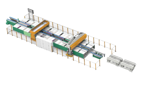
Elevator car-bottom and car-structure assembly
An elevator project might involve part locating, clamping, automatic riveting, material handling and data storage. Simitch first determines whether each connection is part of a structural, safety-relevant or non-structural assembly and then aligns the equipment scope with the buyer’s approved joint design.
- Car-bottom, frame or panel drawings and datums
- Joint classification and buyer-approved acceptance criteria
- Handling, fixture and protected-surface requirements
- Existing line sequence and control interface
- Required operating records and inspection handoff
Rail-transit and long-part assembly
Rail projects often separate vehicle-body structural requirements from brackets, panels, ducts, cabinets and other assemblies. That classification matters because the machine layout cannot prove the fatigue, crash or service performance of a joint.
- Part function and structural classification
- Vehicle or subsystem acceptance route
- Long-part support, indexing and transfer
- One-sided or two-sided joining access
- Sample, sectioning, strength or fatigue test responsibilities
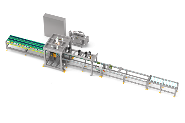
Related large-part and busbar experience
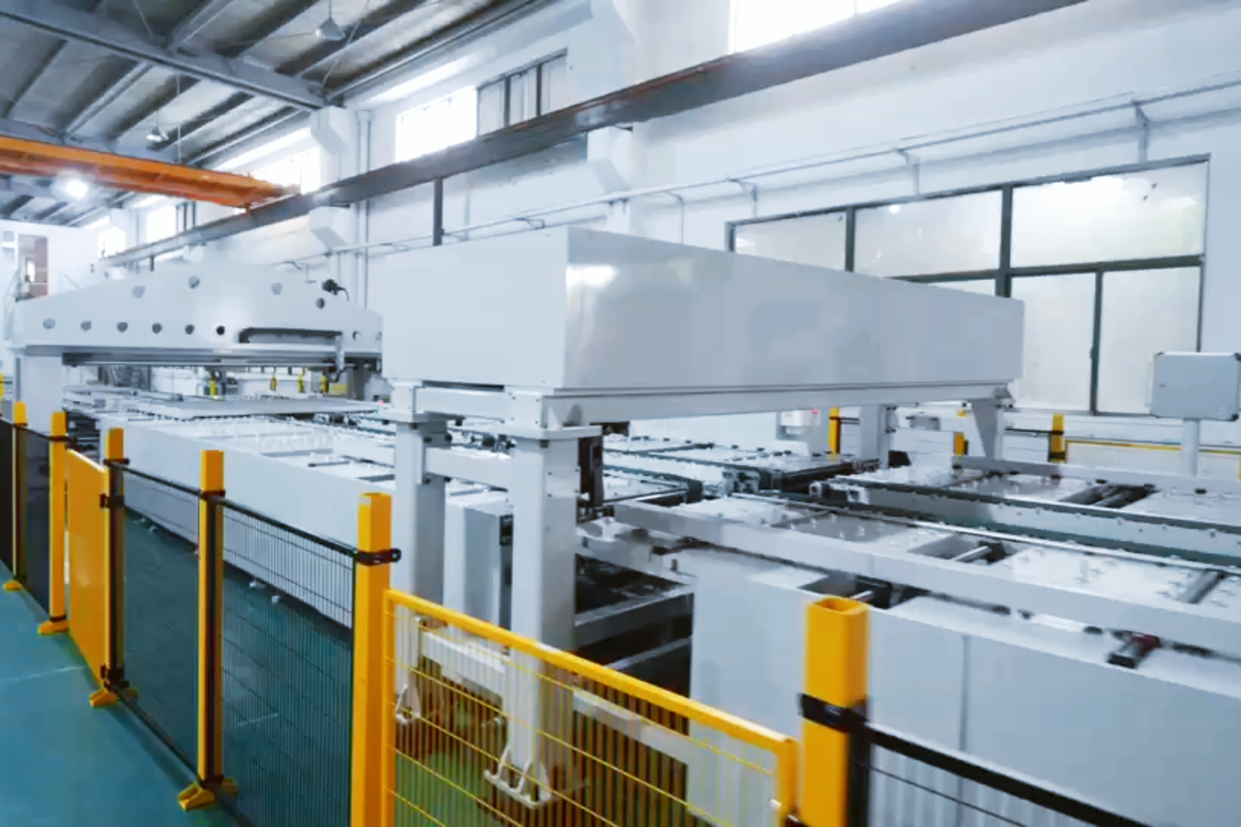
Supplied long-part material shows modular stations, monitoring, multiple control units, remote access and force-related quality functions. It is useful engineering experience for material handling, but it is not presented as a rail-transit case unless the buyer confirms the part and end use.
Remote access needs a written boundary
Remote access becomes a governance risk when authorization, session control and retained data are undefined. Simitch and the buyer should agree users, approval, connection method, logs, confidentiality and shutdown conditions before commissioning.
Build a Complete Riveting System Around the Joining Operation
One riveting head is only part of an automated manufacturing cell. Dependable proposals join the fastener, feed path, fixture, motion, controls, safety and inspection handoff into one operating sequence.
Cell architecture
01
Rivet storage, orientation and rivet feeding
02
Setting tool, die support and force control systems
03
Fixture, clamps and part-presence sensor logic
04
Robot or guided motion and collision-clearance review
05
Guarding, interlocks, modes and operator access
06
Control, recipe, alarm and data collection functions
A robotic riveting system must also provide safe recovery when a rivet does not feed, a part is absent or an interlock opens. More automation is not always the standard fix; better access, clearer diagnostics or a manual recovery step may work better.
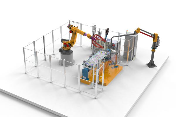
Control and changeover scope
Preset layouts and quick-change elements can reduce setup work, but only when the fixture, tool, program and verification sequence are treated as one change. A changed recipe without a confirmed physical setup is a quality risk.
01
Select the approved part program.
02
Install or confirm the fixture and tooling set.
03
Verify fastener, die and access conditions.
04
Run the agreed first-part checks.
05
Release production under the approved control plan.

Select the Riveting Process by Access, Materials and Quality Needs
Mixed-material capability cannot be assumed for self-piercing riveting. Suitability is not automatic: upper-sheet strength, brittleness, thickness, rivet geometry, die support and the required joint property can change the result.
Technical background: A peer-reviewed self-piercing riveting overview. Its publication date and scope are shown by the source; project approval still depends on current, part-specific tests.
Request a Joint Feasibility Review
Joining route
Access and preparation
Key project inputs
Validation focus
Self-piercing rivet / SPR
Tool on one side and die support on the other; no predrilled hole in the normal process
Material order, thickness, strength, coating, rivet and die
Head position, interlock, remaining bottom thickness, section and strength tests
Blind rivet
Installation from one accessible side through a prepared hole
Hole, grip range, fastener, mandrel handling and backside condition
Setting result, retained mandrel condition and joint test plan
Clinching
Punch and die access; formed interlock without a separate fastener
Material ductility, stack, tool geometry and surface requirements
Interlock geometry, bottom thickness and joint strength
Weld
Process-specific electrode, torch or energy access and heat management
Alloy, coating, fit-up, heat input, distortion and inspection route
Qualified procedure, heat-affected result and applicable inspection
Orbital riveting
Access to form an existing rivet or post with a controlled tool path
Fastener geometry, forming allowance, support and force required
Formed head, component movement and functional test
Engineering validation required
Material-stack changes can invalidate a self-piercing riveting setup that worked on another part. Simitch asks for the actual materials, thicknesses, orientation and acceptance method before treating a process as approved.
Do not force a repair-tool keyword
This is an industrial riveting machine page, not an automotive collision-repair tool guide or an aerospace fuselage and body panels application page.
Light-duty and heavy-duty are not specifications
Those labels do not define force, reach or joint capability. Actual parts and a validated process window do.
Ask for the test chain
Request samples, process records, cross-sections and mechanical tests that match the joint’s role instead of relying on a generic machine label.
Monitor, Record and Review Each Riveting Operation
Force monitoring without a validated joint window can create false confidence. Recorded process curves can show whether riveting followed an expected path, but they do not automatically prove final joint strength because the signal-to-property relationship changes with the material stack and failure mode.
Process-evidence boundary
A peer-reviewed joint-failure overview supports connecting process monitoring to part-specific joint evaluation instead of treating monitoring as a substitute.
Each process curve is evidence about the setting event. An approved joint still needs a correlation and acceptance plan.
What independent evidence says
A 2024 peer-reviewed study monitored force and displacement for two material combinations and evaluated how signal features related to maximum tensile load. Shop-floor joint evaluation in the same paper also used destructive section, peel and tensile checks.
The limitation matters
TWI describes force-versus-displacement as a useful indicator and allows comparison with an experimentally established tolerance band. It also warns that correlation between monitor indications and joint properties may not be precise.
What the project must define
- Which signal or operating state is captured
- How the acceptable window is established
- Which part, joint and rivet identifiers are stored
- What happens after a warning or failed cycle
- Which destructive or non-destructive inspection supports release
- Who owns data retention, access and change approval
Validate the Application and Simitch Capability Before Build
On a new international site, trust language needs evidence. Simitch separates facts available now from the documents, samples and acceptance records that belong in the project file.

Established in 2006
Suzhou Simitch Machinery Co., Ltd. began as a mechanical equipment manufacturer focused on sheet-metal connection machinery.
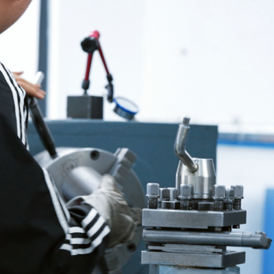
Technology development
Simitch moved from introduced clinching technology toward independent research and development in clinching and precision pressing.
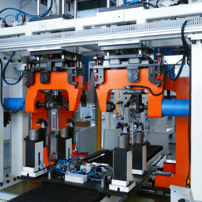
In-house production
Simitch reports independent production of key equipment and core parts, plus independent trademarks and multiple technical patents.
STAGE 01
Review
Drawings, samples, line layout and joint role.
STAGE 02
Confirm
Materials, rivet, access, tests and interfaces.
STAGE 03
Propose
Process, tooling, motion, fixture and control scope.
STAGE 04
Accept
Factory test matrix, evidence and sign-off rules.
STAGE 05
Deliver
Site work, training, spares and service boundary.
Verified now
- Brand history supplied by Simitch
- Six application and equipment assets
- Modular, monitoring, data and remote-access functions shown in supplied materials
- Independent safety and process-monitoring references
Request before purchase
- Patent numbers relevant to the proposed equipment
- Applicable certificates and current validity
- Factory capability evidence for the selected build
- Test samples and signed acceptance matrix
- Warranty, service area and response terms
Safety and standards are application-specific
OSHA notes that there is no single robotics-specific OSHA standard and points integrators to applicable machine, hazardous-energy and robot-system requirements. Final safety files depend on the buyer’s jurisdiction, plant rules and risk assessment.
Plan Riveting Machine Price, Lead Time and Delivery Scope Together
A low machine price is not a comparable project price when tooling, guarding, controls and acceptance are missing. Simitch prepares a useful quotation only after the same input set is used to define technical scope, delivery boundary and commercial assumptions.
Bronze total-cost framework: no unsupported payback claim
- Baseline the current labor, rework, scrap, downtime and inspection steps with buyer-owned records.
- Add equipment, fixture, integration, utilities, installation, training, spares and service scope.
- Model expected production runs and changeovers with agreed assumptions, not a generic industry percentage.
- Track the assumptions that still need a trial, sample or site survey.
Cost or schedule driver
Why it changes the proposal
Input needed
Part and joint
Set reach, support, tool access and joining method
Drawing, sample, stack and joint schedule
Motion and handling
Set robot, guided axes, transfer and operator tasks
Layout, load/unload method and variant flow
Tooling and fixture
Set clamping, datums, change parts and protected surfaces
Reference scheme and changeover plan
Rivet feeding
Set storage, orientation, replenishment and recovery
Fastener specification and consumption pattern
Quality control
Set sensors, result logic, data, testing and traceability
Control plan and acceptance criteria
System integration
Set plant signals, network, safety and upstream/downstream handshakes
Interface list and site standards
Delivery and support
Set factory testing, site work, training, spares and service
Installation site and responsibility matrix
What buyers get wrong
Lowest equipment price does not always mean the lowest-cost project. Ask every vendor to quote against the same fixture, guarding, control, test, installation and service boundary.
Included
List the machine, standard tooling, control cabinet, guarding, documents and factory test in plain terms.
Optional
Price plant interfaces, vision, extended data, extra fixtures, spares and site services as named choices.
Buyer supplied
Identify utilities, foundations, network access, samples, production materials and on-site lifting before order.
Frequently Asked Questions
Yes, when the existing line has a workable part reference, access path, safety boundary and control interface. Simitch needs the current layout and sequence before confirming an integration method.
Start with the identifier, signal, result and plant interface. Hardware and software follow from that record.
Compare part mix, reach, access, changeover, fixture, recovery and quality-record needs. Robot flexibility helps with variation, while stable work may suit a dedicated station with fewer moving interfaces.
No. Test the real material stack, rivet and die together.
Not by itself. Monitoring can flag deviations after engineers establish a process window, but the signal still needs correlation to the joint property that matters. Section, peel, tensile or another agreed method may form part of that evidence.
Programs, fixtures and quick-change elements can support model changes, but every change needs a physical setup check. Include tool identification, recipe control, first-part release and the response to a failed verification in the acceptance plan.
Part handling, fixtures, feeding, guarding, controls, data, testing and delivery scope define the price. Send a common scope to all suppliers.
Yes, subject to an approved access method, permissions, logs and shutdown rules.
Use representative parts and a written sequence that covers normal operation, foreseeable faults, safety checks, changeover and process records. Define joint evidence, sample quantities, pass criteria, open-item handling and retest responsibility before the test. Factory acceptance testing cannot close issues absent from the acceptance criteria.
No. Final specifications come from the approved project scope.