Get in touch with Suzhou Simitch Machinery Co., Ltd Company

Hot-Melt Connection Equipment (FDS): Flow Drill Screwdriving Systems and Molds
SIMITCH builds flow drill screw equipment, hot-melt connection molds and the line integration around them. A flow drill screw is a thread-forming fastener that friction-heats the sheet until the metal flows, and that is how these systems set a threaded joint from one side, into closed extrusions where a two-sided C-frame has nowhere to go. We have supplied clinching machines, riveting and self-piercing riveting equipment since 2006, so our first question is whether your part needs FDS at all.
Request an Engineering Review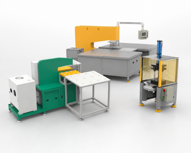
- 1 side Access needed. No counter nut, no C-frame.
- 2–4 Thin sheet layers joined per screw
- 6 mm Stack ceiling without pre-drilling
- 8.3 / 12 N·m Installation torque ceiling, M5 / M6
- 1–4 s Cycle time per joint, stack dependent
- 3 lines Equipment, molds, intelligent integration
Why Closed Extrusions and One-Sided Access Break Conventional Joining
A car body or a battery tray built from hydro-formed tubes and aluminium extrusions has one property that reorders your whole joining plan: only one face is reachable. Clinching and self-piercing riveting both need a punch and a die held in opposition, and that opposition lives inside a C-frame. Where the frame cannot enter the profile, the process is out, no matter how good the joint would have been.
Two-sided mechanical joining fails on closed sections because the die has to sit behind the joint. Flow drill screwdriving, also called thermal friction drilling in the machining literature, removes the back-side tool entirely: the conical tip penetrates the top sheet under axial load and high screwdriver speed, forms its own extrusion with no chips, then completes thread forming and tightening in the same stroke. EJOT ATF states the case in one line: one-sided accessibility provides for assembly into hollow profiles such as hydro-formed or aluminum extrusions.
Resistance spot welding is the other incumbent, and it carries three separate penalties on aluminium. Skovron and colleagues list them: the heat-affected zone lowers the structural performance of the joint, two-sided access limits design freedom, and weld variation produces inconsistent production. Kumar and Hynes add the failure modes of the older threaded fixes, where rivet nuts and expansion nuts lift and twist under load and weld nuts distort the sheet with heat.
- Back side unreachable, and no room for a C-frame → the joint has to be set from the front.
- Material combinations of steel, aluminium and magnesium in one stack → one fastener and one machine, with parameters changed for different materials rather than tooling.
- Service, repair or recycling requires the joint to come apart → a metric thread beats a formed button or a rivet.
Lightweight construction created that gap and keeps widening it. Lightweighting cuts energy consumption in transport, so carmakers moved to multi-material bodies faster than two-sided joining could follow, and the automotive sector now runs mixed stacks that no single process covers. FDS grew out of exactly that pressure. Roughly three decades of development followed its arrival in the 1990s, and it became the leading alternative to self-piercing riveting when the joining back side is not accessible, in the words of the Clemson University patent family that documents the process.
Hold on to that sentence. It is the alternative for a specific geometry, not a general upgrade — and in e-mobility, where an electric battery enclosure has to be opened again for module service, geometry and serviceability arrive together.
Getting this wrong is expensive because the failure surfaces late. A stack of 2 to 4 layers running to about 6 mm sits near the ceiling of what one-sided screwdriving can reach, and a top sheet over 2.0 mm in high-strength steel changes the process plan again. Discovering either constraint after the tooling is cut moves the fixture, the robot path and the cycle-time plan together.
SIMITCH has built the two-sided processes and the one-sided one since 2006 and has shipped equipment to 50 countries, whereas a single-process supplier has to make your geometry fit the one machine it sells. That is the difference between a selection conversation and a sales pitch.
SIMITCH Hot-Melt Connection Equipment: System Solutions, Molds and Integration
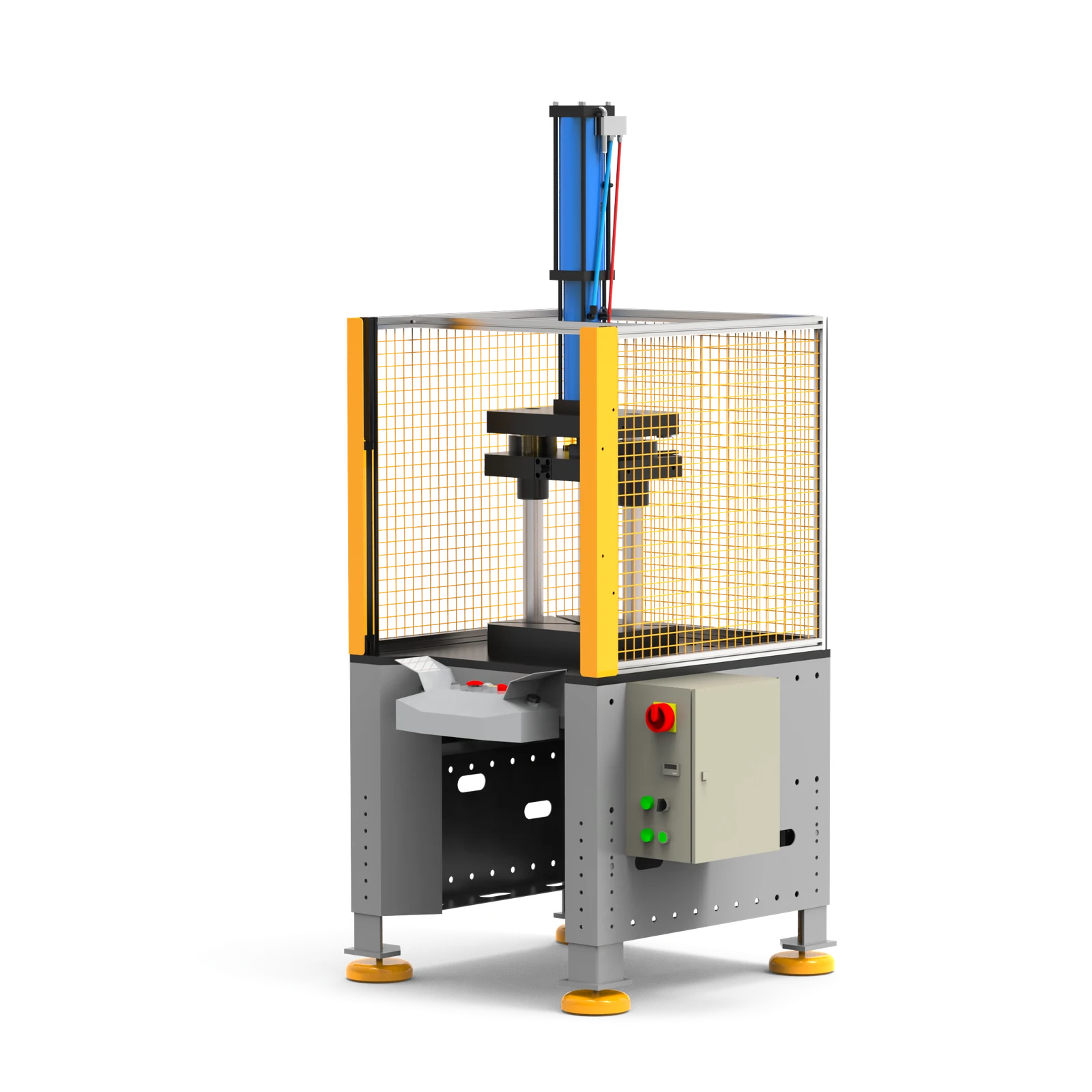
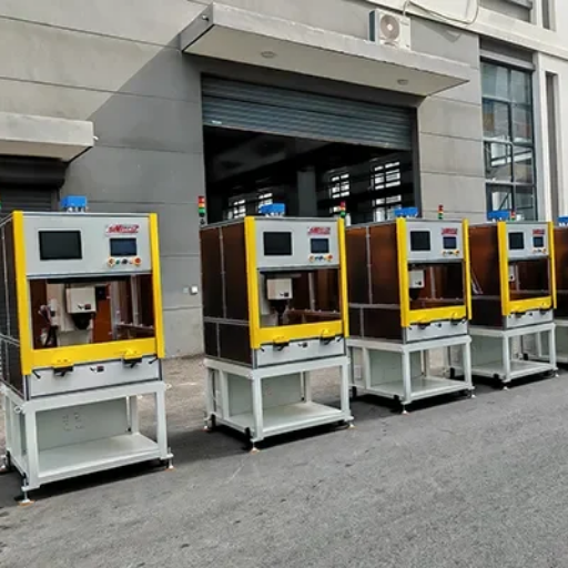
Three lines sit under this product family, and each one needs different inputs from you before a quote means anything. Our FDS flow drill screw unit is the spindle side, and it drives an FDS® flow drill fastener. Molds and tooling are the part side. Intelligent integration is the line side, where the unit meets a robot, a fixture and your quality network.
Our hot-melt connection molds and screwdriving units are built as one package, because downholder geometry and mold geometry have to agree on where the sheet is supported. Tell us the joint, and we design backwards from it.
- FDS equipment — spindle, downholder, feeding, control.
Quote inputs: sheet thicknesses per layer, layer count, material grade, target cycle time. - FDS molds and support tooling — the part-side fixture that resists the axial load.
Quote inputs: part geometry near the joint, clamp positions, accessibility envelope. - Intelligent integration — robot interface, joint sequencing, data output for your traceability network.
Quote inputs: robot make, cell layout, the data fields your line records per joint.
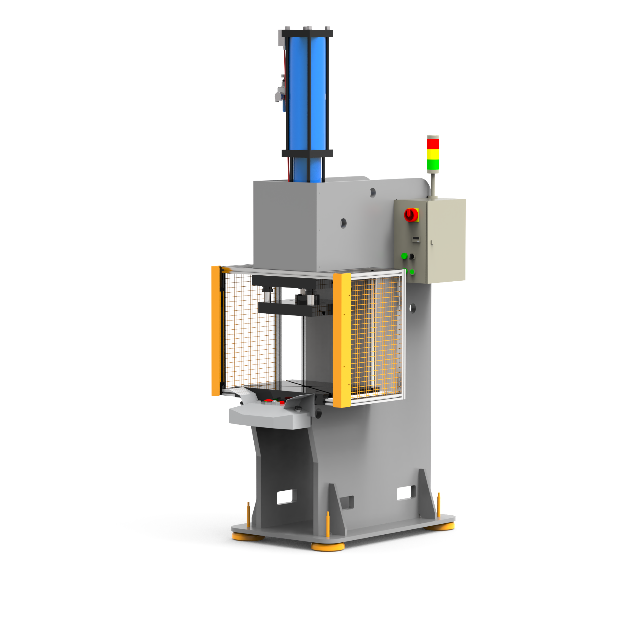
Four variables decide whether a flow drill machine produces a joint or a scrapped panel, and a joining system that misses any one of them will scrap panels quietly: rotation speed, tightening torque, axial load and depth. Semblex, which makes the fastener rather than the equipment, puts the requirement on the record: FDS assembly requires high-speed automated drive systems that control and adjust speed, torque, axial load, and depth throughout the multi-stage installation process. A downholder, the pressure foot that resists movement of the top layer, is a standard component of most FDS machines according to the Clemson patent record.
| Subsystem | What it decides | What we ask you for |
|---|---|---|
| Screwdriver spindle | Speed profile across the six phases, tightening torque, depth window | Stack build-up, material grade, torque class |
| Downholder / pressure foot | Whether the top sheet stays put while the extrusion forms | Accessibility envelope around the joint |
| Feeding unit | Screws per minute, and how often the line stops | Screw type, head style, annual volume |
| Control and data | Per-joint records for your quality network | Data fields, protocol, joint category |
Feeding is where throughput is quietly won or lost, and the patent says why in a single aside: its own process-time comparison excludes the finding of the screw, because that time varies by equipment manufacturer. Everything after touchdown is physics. Everything before it is your supplier’s engineering, which is why we quote system solutions rather than spindles.
SIMITCH publishes force figures for neighbouring families, and they are not FDS specifications: AT/HZ split-type pneumohydraulic cylinders in 15 models from 13 kN to 1,030 kN, BS/BT cylinders from 11 kN to 970 kN, the BP precision assembly servo press from 10 kN to 200 kN, and servo riveting at 80 kN with 200 mm stroke, 0 to 333 mm/s, plus or minus 2 percent force accuracy and 0.01 mm repeat positioning.
Those numbers tell you what our machine builders hold to. They say nothing about an FDS spindle, and we will not present them as if they did.
See the AT/HZ split-type series and the BP servo press we build for precision assembly
Selection criteria for the spindle come from the fastener, not from a catalogue. Flow drilling needs a high screwdriver speed and a defined pressure force, while thread-forming and final tightening need high torque, so the drive has to move between two very different duty points inside one cycle. That is a fastening technology constraint, and it is the same for every builder.
Flow Drill Screwdriving vs Clinching vs Self-Piercing Riveting vs Resistance Spot Welding
Nobody sells you a joining process. They sell you the one they make. We make four of them, which is the only reason this section can exist.
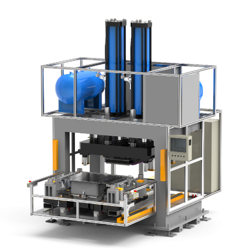
The Joining Access Triangle
Three questions settle most of it, and they settle it before cost enters the conversation.
- Can a tool reach the back face of the joint? If yes, two-sided joining technologies stay on the table.
- Is there room for a C-frame deep enough to carry punch and die to that face? A closed extrusion usually answers no.
- Does the joint have to come apart for service, repair or recycling? A formed thread does that. Clinch joints and rivets do not.
Answer no to question one or two, and yes to question three, and FDS stops being a choice and becomes the only route. Answer yes to one and two and no to three, and you should be buying clinching, not screwdriving.
| Criterion | Flow drill screwdriving | Clinching | Self-piercing riveting | Resistance spot welding |
|---|---|---|---|---|
| Access required | One side | Both sides | Both sides | Both sides |
| Back-side tooling | None; no counter nut | Punch and die | Rivet and die | Opposing electrode |
| Consumable per joint | One screw | None | One rivet | None; electrode dressing |
| Comes apart for service | Yes, standard metric screw | No | No | No |
| Heat into the part | Frictional; about 280 °C peak in published trials | Cold forming | Cold forming | Resistance heat and a heat-affected zone |
| Stack ceiling | 6 mm without a clearance hole; about 7 mm overall | Set by material ductility | Set by rivet and die pairing | Set by electrode and current |
| Material boundary | Aluminium and low-strength steel; higher-strength steels not feasible one-sided | Needs formability to draw the button | Rivet and die changed per material pair | Aluminium melts below 800 °C, so control tightens |
| Joint loading | High pull-out and shear capacity from deep thread engagement | Interlock in shear; weaker in peel | Mechanical interlock, high fatigue life | High static strength, lower fatigue life |
| Cycle time per joint | 1–4 s, stack dependent | Press stroke governed | Setting-force governed | Weld schedule governed |
| Tool change on material change | Parameters only | Punch and die set | Rivet and die combination | Electrode and schedule |
Process Trade-Offs
Cost Position: What We Will Claim
Two rows in that table deserve a second read from procurement. Clinching consumes nothing per joint and needs no feeding unit at all, which is a genuine cost advantage and we will say so when it applies. FDS buys you one-sided access plus serviceability, and it charges you a screw and a feeder for the privilege. Friction welds and friction element welding sit in the same family of alternatives and carry their own trade-off between speed and equipment cost.
The trade-off is not subtle. If your back side is reachable and the joint never has to come apart, we would rather sell you a clinching machine and keep the FDS line for joints that genuinely have no second face. A wrongly specified capital line is a problem you live with for years, and it usually starts with a supplier who only had one process to offer.
— SIMITCH Application Engineering Team, Suzhou Simitch Machinery Co., Ltd.Peer-reviewed work says flow drill screws cost more than self-piercing rivets and clinching. It gives no figure, and neither does any equipment vendor we could find. So there is no cost-per-joint number on this page. What we can hand you is the structure of the number: screw unit price, cycle time, feeding method, whether a pre-hole operation survives in the plan, mold life, and the pre-drilling, tapping and nut-fitting stations the process deletes. Run those against your own volumes and the answer stops being marketing.
Cost direction from Liu et al. 2023. No per-joint or total-cost-of-ownership figure exists in public sources, checked 2026-07-30. See also the OSTI record on mechanical joining process parameters.
Cheapest per joint is not always cheapest per line. A joint that is cheaper per piece but forces a pre-drilling station back into the sequence has cost you a workstation, its floor space and its cycle. Such arithmetic is what a four-process view is for, and it is why we would rather route you correctly than sell you whichever process happens to be under discussion. Compare configuration options on clinching machines, or see how a two-sided self-piercing riveting cell is laid out before you commit.
FDS Process Window: Cycle Time, Axial Force and Pre-Hole Thresholds
Most pages in this category publish no numbers at all. Here is the window, with every row traceable to a patent, a peer-reviewed paper or a fastener maker's published statement.
| Parameter | Published value | Source type |
|---|---|---|
| Rotation speed, forming phases | 6,000 rpm in the reported trial | Patent |
| Rotation speed, final tightening | 250 rpm | Patent |
| Axial force, forming phases | 600 N in the reported trial; generally below 4.0 kN | Patent, review |
| Axial force, final tightening | 500 N | Patent |
| Tightening torque | 6 N·m in the reported trial | Patent |
| Installation torque, measured baseline | 5.12 N·m on two 1.3 mm 6063-T5 sheets | Patent |
| Installation torque ceiling | 8.3 N·m for M5; 12 N·m for M6 | Patent |
| Break-loose torque | 5.58 N·m after a 6 N·m final torque | Patent |
| Peak joint temperature | About 280 °C | Patent |
| Sheets per joint | 2 to 4 | Trade press |
| Stack ceiling, no clearance hole | 6 mm; about 7 mm for stacks overall | Fastener maker, patent |
| Pilot hole threshold | Top sheet of high-strength steel thicker than 2.0 mm | Review |
| Extrusion draft length | Up to 3× the original sheet thickness | Trade press |
| Screw mass | 4.0 to 5.0 g | Review |
| Cycle time | 1–2 s excluding screw finding; 1.5–4.0 s whole process | Patent, review |
| Formed female thread | Metric profile per ISO 261 | Standard |
Installation torque is what the fastener needs to form the thread, and it is capped by the torsional strength of a standardised self-tapping screw: 8.3 N·m at M5 and 12 N·m at M6. Push a thicker or harder stack and required torque climbs into that ceiling, so the screw fails before the machine does. Buying a stronger spindle does not move this limit, because the limit belongs to the strength of materials in the fastener itself.
Raise the axial force and process time drops, which is what everyone wants. It also drops part temperature and raises installation torque, which is what nobody wants. Lower the axial force and the tool stays in contact longer, generating more heat and softening the material, at the cost of cycle time.
Thermal assistance shifts the whole curve: pre-heating to 247 °C cut installation torque by 20 percent and process time by 52 percent in published work, and an electrically assisted variant reached minus 18 percent torque and minus 32 percent time from a 128 °C pre-process temperature. All conditions converged near the same 280 °C peak, because a softer stack needs less frictional energy to reach it.
Our FDS Process Window table is not a specification sheet for a SIMITCH machine. It is the physics your part has to live inside, whoever builds the spindle. Our job is to place your stack inside that window, or tell you it does not fit.
Assembly without pre-drilling is the headline claim, and combining friction drilling and thread forming in one stroke is what delivers it. That holds for the standard route and fails in at least three situations, so the flow drill screw process has to be planned rather than assumed.
- A top sheet of high-strength steel thicker than 2.0 mm needs a pilot hole.
- A top layer whose material resists flow-drilling goes to the clearance-hole route instead, where the downholder is no longer required. Even the patent literature concedes that the hole-free approach does not always allow the most efficient assembly in many situations.
- A joint that has to seal needs the sealed screw variant, and that variant requires a pre-drilled clamping part. More on that below.
Running the other way is a second common assumption: that thin material is the easy case. Borgert and colleagues put the opposite in print, that flow-drill screwing still has the disadvantage that mainly thick sheets can be joined due to the need to insert a thread. Thread engagement lives in the draft the screw pushes out of the bottom sheet, and that draft reaches up to three times the original sheet thickness, so a thin bottom sheet gives you a short thread and a weak joint. Cast material adds its own limit, since fastener makers report inconsistent material flow in brittle castings.
What the six phases actually do
Heating by axial end load and high speed, then penetration, then forming of the through-draft, then chipless thread-forming of a metric female thread, then screwing in to full thread engagement, then tightening to a set torque. Four independent sources describe the same six phases, which is unusual agreement in this category. Between phase three and phase four is where a flow drilling screw for high-strength sheet earns its name: displaced material becomes the counter nut instead of waste, and no chips are produced that would then need cleaning out of the assembly. Deep thread engagement in that draft is what turns an FDS® screw into a fastener capable of high-strength joints rather than a sheet-metal screw. Those six phases are one fastening process, from touchdown to release.
Body Shop and Battery Tray: Where FDS Earns Its Place in the Automotive Industry
Two deployment records tell you more about this process than any brochure. One is per-vehicle screw count. The other is what share of a real body shop's joints the process actually carries.
Per-Vehicle FDS Count Benchmark
| Vehicle | Flow drill screws per vehicle | What it implies for a line |
|---|---|---|
| BMW 5 and 7 Series | about 180 | One well-placed cell can carry the volume |
| Lamborghini Gallardo | about 200 | Low volume, high mix, manual-adjacent |
| Mercedes-Benz SLS AMG | 581 | Multiple stations, sequencing matters |
| Cadillac CT6 | 745 | Feeding reliability becomes the constraint |
| Audi A8, fourth generation | 885 | Dedicated FDS stations with buffered feeding |

Share of joints is the second number, and more useful than the count. On the first aluminium-bodied Ford F-150, the truck was assembled with approximately 2,000 rivets against 5,000 spot welds in the previous steel version, and flow-drill screws carried about 15 percent of the joints, used where backside access was limited or single-sided. The rest went to self-piercing rivets, structural adhesive, clinching and laser welding. General Motors has used seven joining methods on an aluminium structure.
That is the strongest argument for a supplier who builds more than one process. Ford's body construction chief engineer, Ron Ketelhut, described the design value directly: flow-drill screws let them run stack-ups changing from thick to thin to thick, which gives more design freedom than just using a rivet. He also flagged the cost of that freedom in one line that belongs on every quality plan: Aluminum joining requires a lot more process control than steel.
- Battery trays and enclosures for electric vehicles — one-sided access into extruded frames, and joints that may need opening again for module service.
- Body-in-white underbody and framing — mixed stacks of steel and aluminium in a space frame, where assembly processes have to tolerate stack changes station to station.
- Appliance, aerospace and general machine building — the same geometry problem at lower volume.
In the 30 years since FDS arrived, the risk in this arithmetic has not changed: at 1.5 to 4.0 seconds per joint, a 745-screw vehicle spends real line minutes on fastening alone, and a feeding fault at that count stops the station rather than slowing it. SIMITCH builds the spindle, the mold and the integration in-house, which is why we quote station count and feeding architecture rather than a spindle price. Unlike a fastener catalogue, a station plan can be checked against your takt before anyone spends money.
When Not to Use Flow Drill Screwdriving
Every process page lists advantages. This section decides whether you waste a capital budget, so it sits on the same page as the sales copy.
Higher-strength steels, joined from one side.
The patent record is blunt: one-sided joining of higher strength steels is not possible, with FDS limited to low-strength steel or aluminium. Boron steel at 1,500 MPa would not let the fastener through at all in published trials without electrical assistance.
Stacks beyond the window.
About 6 mm with no clearance hole, about 7 mm overall.
Thin bottom sheets.
Short draft, short thread engagement, weak joint.
Brittle castings.
Where material flow becomes inconsistent.
Pure speed contests.
FDS is slower than resistance spot welding, self-piercing riveting and friction element welding, and half of its process time sits in the first three forming steps. Time you win is in the stations you delete, not in the joint itself.
Surfaces that must stay flush on both faces.
Since the joint leaves a protrusion on each side.
| Source | Position |
|---|---|
| Peer-reviewed review, widely cited | FDS shows good waterproof and gas-tight behaviour without extra sealing elements |
| Fastener distributor, current product page | The resulting connection is both water- and gas-tight |
| Fastener maker, current product page | Joints are not leak-resistant, listed under traditional flow drill screw limitations, directly above a link to its own upgraded screw |
| Holder of the FDS® trademark | Sells a separate sealed variant with a pre-assembled embossed aluminium washer, rated for a waterproofing function of 1 m water column over 24 hours |
Sealing is not a property of the process. It is a property of the fastener variant, the head design and the parameter window, which is why three independent sources describe the same mechanism: a recess or undercut under the head catches material flowing back up, and cooling contraction pulls the formed thread into a tight fit. Under favourable conditions that joint is dense. Being dense is not the same as being qualified against a stated head of water.
The honest version, and what it costs you
If the trademark holder needs a dedicated washer-sealed screw to publish a 1 m water column figure, the plain joint was never specified as a seal. And that sealed variant carries a line we would rather you read from us than discover at the runoff: Pre-drilling of the clamping part is necessary for this application. Buying a specified seal means giving up the no-pre-drill advantage that brought you to FDS in the first place. It also lands on the equipment, because the washer is captive but rotatable and has to be 1 mm smaller than head diameter for automated feeding, so your feeder specification changes too.
Three steps, then, if the joint has a sealing function. Run a coupon trial on your real stack. Leak-test it against your own specification rather than anyone's general claim. Then price the pre-drilling operation and the feeder capability into the plan before the capital request goes in.
Sealing joint in the plan? Talk to our application engineering team before the fastener is chosen, not after.
Conformity: CE, Machine Safety and How VDI/VDE 2862 Sets Your Monitoring Specification
No FDS-specific ISO standard exists. What governs this equipment is machine safety law on our side and a screwdriving guideline on yours, and knowing which is which saves an audit cycle.
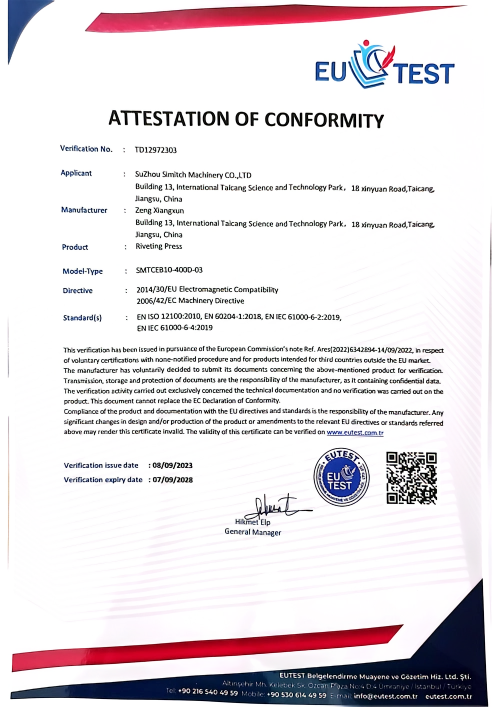
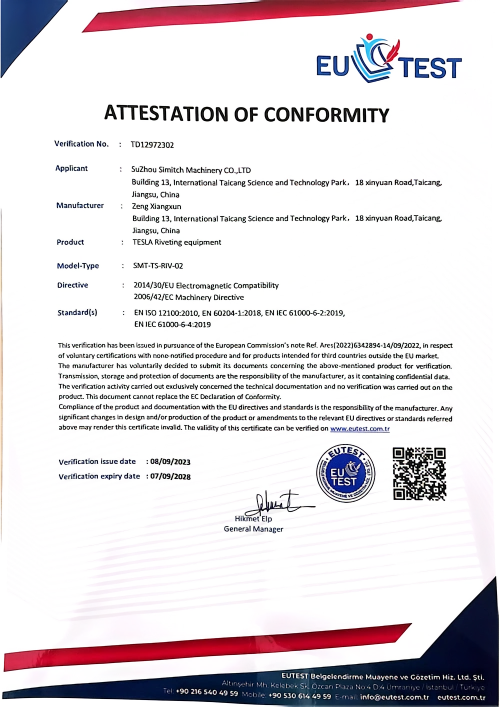
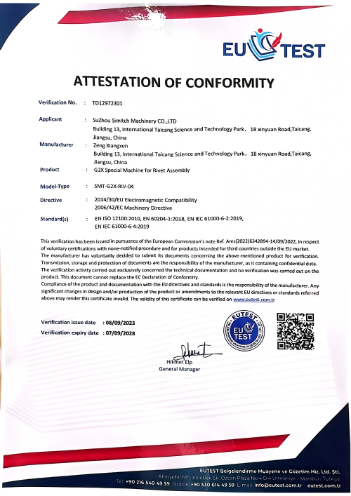
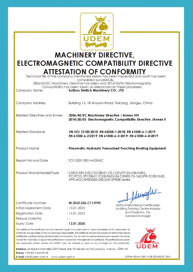
CE conformity
Declared for the machinery we supply
3 attestations
Attestations of conformity on file
ISO 12100
Method behind a machinery risk assessment
VDI/VDE 2862
Joint categories A, B and C
50 countries
Export coverage since 2006
CE conformity for machinery rests on a documented risk assessment, and ISO 12100 is the standard defining how that assessment is done. SIMITCH holds CE conformity plus three attestations of conformity for the equipment families we supply. We do not publish certificate numbers on a web page, and any supplier who does should still be asked for the file itself.
VDI/VDE 2862 regulates industrial use of screwdriving systems and tools. Part 1 covers automotive minimum requirements; Part 2 covers plant and mechanical engineering. It sorts joints into three risk classes, and the class drives what your equipment has to measure and record. That is how high process reliability becomes provable rather than asserted.
Failure in that guideline means something specific: loosening, breakage of the bolt, or loss of the bolt or nut. For a Category A joint the recorded variable is normally tightening torque, and its ceiling belongs to the fastener rather than the spindle: 8.3 N·m at M5 on a stack running to 6 mm. Unlike a certification claim on a brochure, a torque-and-angle record per joint is something your auditor can read.
SIMITCH runs the machinery risk assessment in-house against the ISO 12100 method, and the conformity file travels with the machine. Tell us the category with the RFQ and the control specification writes itself. Leave it out, and you will either overpay for traceability you do not need or discover at the buyoff that you cannot prove the joints you already made.
VDI/VDE 2862 JOINT CATEGORIES
| Category | Definition | What the equipment must deliver |
|---|---|---|
| A | Failure likely to destroy the system and endanger life and limb | Continuous monitoring, measured control variable, full traceability per joint |
| B | Failure causes malfunction or a standstill | Monitoring with recorded process data and a defined reaction on deviation |
| C | Non-critical joints | Simpler tooling with limited monitoring may be sufficient |
Need the conformity file that ships with the machine? Ask us for it directly — we will send what exists and say plainly what does not.
Governing documents: ISO 12100:2010 and VDI/VDE 2862 Part 1.
Resources
FDS Engineering Calculators and Selectors
All buyer roles
FAQ: Flow Drill Screwdriving Equipment and Molds
01
What is flow drill screwdriving used for in the automotive industry?
Body-in-white framing, underbody, closures and battery enclosures, wherever a joint has to be set from one face. The flow drill method carried about 15 percent of the joints on the first aluminium-bodied Ford F-150.
02
How thick a stack can flow drill screwdriving join without a clearance hole?
Six millimetres is the published ceiling from the fastener side, and the patent literature puts the general stack limit at about 7 mm. Both figures assume the top layer suits flow drilling. Beyond that window you move to a clearance-hole route or to a different process entirely, and the honest answer at RFQ stage is a coupon trial on your real material rather than a table lookup.
03
When does the top sheet need a pre-hole?
When it is high-strength steel thicker than 2.0 mm, or when its material behaviour makes flow drilling unreliable.
04
Is a flow drill screw joint leak-tight?
Four authoritative sources do not agree, and you should know that before designing around it. A peer-reviewed review and a fastener distributor both describe the joint as water- and gas-tight; a fastener maker lists it as not leak-resistant; and the holder of the FDS® trademark sells a separate sealed variant with an embossed aluminium washer rated at 1 m water column over 24 hours. Read together the picture is consistent: a plain joint can be dense, but a specified seal is a different fastener, and that fastener requires a pre-drilled clamping part plus a feeder able to handle a captive rotatable washer. If the joint carries a sealing function, run a coupon trial and leak-test it against your own specification.
05
Can flow drill screw joints be taken apart and re-fastened?
Yes. Thread forming produces a metric female thread, so a standard metric screw goes back into it for service or repair, and parts separate for recycling. Clinching and riveting cannot offer that.
06
Do I need FDS, clinching or self-piercing riveting for my part?
Run the three questions in the Joining Access Triangle above. Reachable back face plus no service requirement usually points to clinching, which consumes nothing per joint.
07
What do you need from us to quote an FDS system?
The nine inputs listed in the procurement section, and realistically the first five settle most of the design: thickness per layer, layer count, material grade, surface treatment and joint requirements. Add cycle time, annual volume and joint category, and we can size the spindle, the downholder and the feeding unit rather than guess at them. Send only a part number and expect a range instead of a quote.
08
What drives the cost of an FDS joint?
Screw price, cycle time, feeding method, whether a pre-hole operation stays in the plan, mold life, and the depth of monitoring your joint category demands. Set against that, the operations the process removes. We publish the variables rather than a figure, because no credible public source publishes a per-joint cost for this process and inventing one is not an option.