Get in touch with Suzhou Simitch Machinery Co., Ltd Company

Split-Type Pneumohydraulic Cylinder
Split-Type Pneumohydraulic Working Cylinders: AT & HZ Series
A split-type pneumohydraulic cylinder puts the compact working cylinder at the tool while its air-oil drive can sit where the machine layout allows. Simitch AT and HZ series cover verified nominal force points from 13 to 1030 kN, with separate pressure bases and drive-family pairings.
AT: 13-1030 kN at 400 bar
HZ: 48-492 kN at 250 bar
MPS and HMPS drive options
Solution snapshot
01
15 models
Nine AT and six HZ working-cylinder models create a source-backed shortlist before stroke and mounting are finalized.
02
2 pressure bases
AT force is listed at 400 bar; HZ force is listed at 250 bar. Never mix or silently convert those values.
03
Split layout
Cylinder, hydraulic line, and air-oil drive are selected as one system while remaining physically separate.
04
Tool-side packaging
Remote drive placement can free the designer from locating the full power package directly above the tooling.
05
Short power-stroke fit
Applications that need a high-force working phase after approach can suit this architecture, subject to the final sequence design.
06
Quote-ready inputs
A six-input RFQ card ties process force, stroke, duty, utilities, layout, controls, and safety into the model decision.
AT & HZ Series Engineering Resources
AT & HZ Nominal-Force Model Selector
Enter a process-force target and selection margin to find the smallest listed model whose catalog force meets the resulting nominal-force threshold.
AT & HZ Three-Model Comparison
Compare three catalog rows across pressure, force, oil, hose, and reference-dimension fields before requesting drawings and a configured quotation.
03
6-Input Split-System RFQ Builder
Build a copyable engineering brief that separates confirmed application conditions from open questions, giving Simitch enough context to review the working-cylinder family, nominal-force point, stroke, drive starting point, layout boundary, controls, safety scope, and quotation inclusions.
Build RFQ
Put the Working Cylinder at the Tool and the Drive Where It Fits
A conventional package can force the machine builder to reserve one large envelope for power generation and pressing. With a split architecture, the working cylinder follows the load path while the drive can sit where service access and line routing make sense.
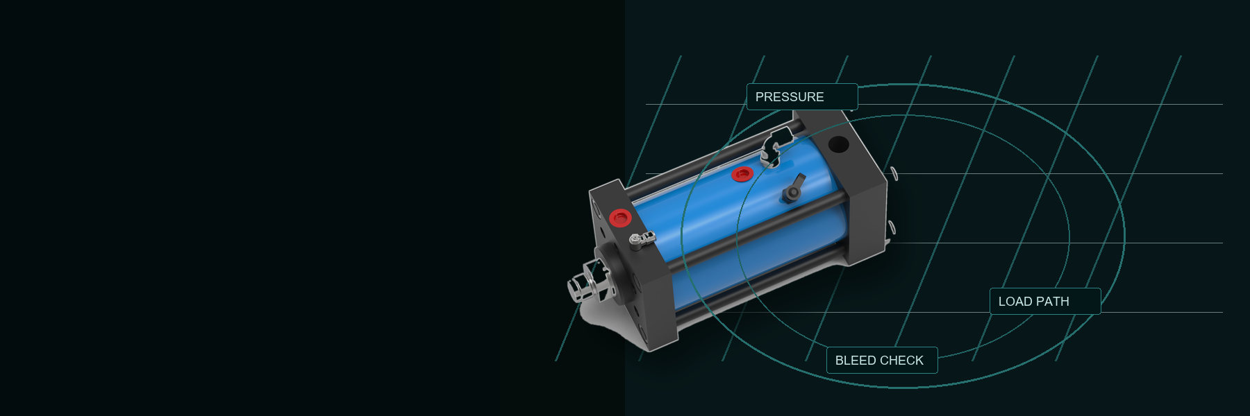
Three traps to resolve before a model is released
01
A buyer may choose the right nominal-force row and still miss the workpiece target when actual pressure and load geometry are undefined.
02
Air trapped in the oil circuit can turn commissioning into repeated bleeding and service work.
03
A split working cylinder is not a complete press; the drive, line, controls, tooling, structure, and guarding remain in scope.
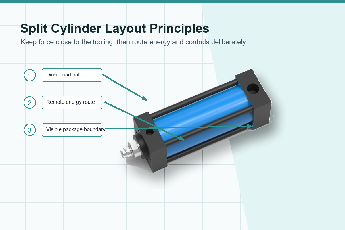
Place force near the process
Start from the tooling and frame geometry, then choose a working cylinder whose mounting and rod axis support a direct load path.
Route the energy path deliberately
Remote drive placement creates layout freedom, but hose, fittings, oil volume, fill point, and bleed access become engineering inputs.
Keep the package boundary visible
A working cylinder is not a complete press. Controls, sensors, guarding, structure, tooling, valves, and commissioning remain in the machine scope.
Where the split approach earns attention
Tooling leaves little room for a full power package.
High working force is needed over a shorter process stroke rather than the entire travel.
Drive access matters while the cylinder sits inside a guarded or crowded station.
A machine builder wants to plan the cylinder, drive, hose, controls, and frame as separate serviceable elements.
Separation also adds responsibilities. Poor line planning, trapped air, side loading, an undefined return load, or incomplete controls can erase the packaging benefit.
How the Separate Drive, Oil Line, and Working Cylinder Work Together
Compressed air powers the drive, which creates hydraulic pressure and usable oil volume for the tool-side cylinder. Exact approach, contact, boost, dwell, and return behavior depends on the circuit, valves, sensors, and machine logic.
The five-part energy and control path
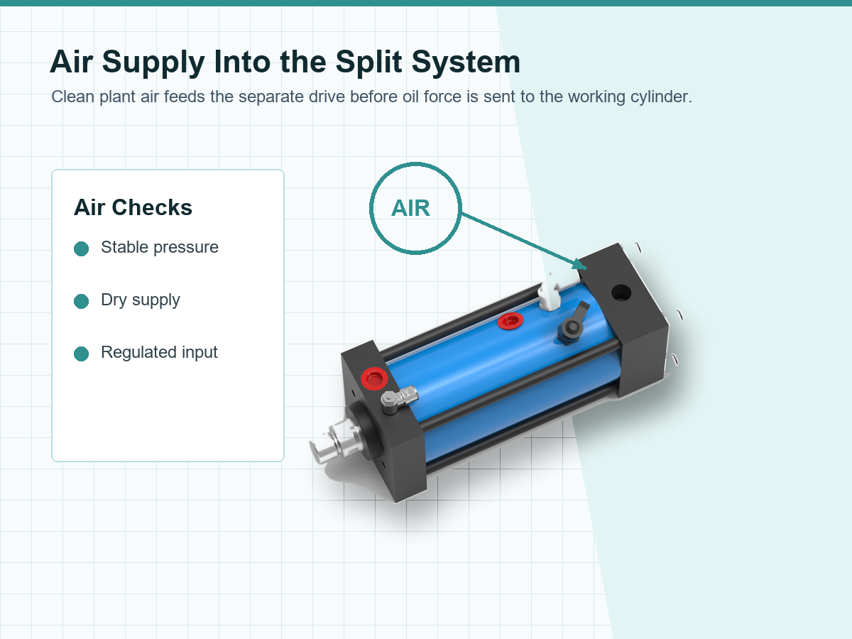
Air supply
Define available pressure, flow, quality, isolation, and pressure stability at the machine.
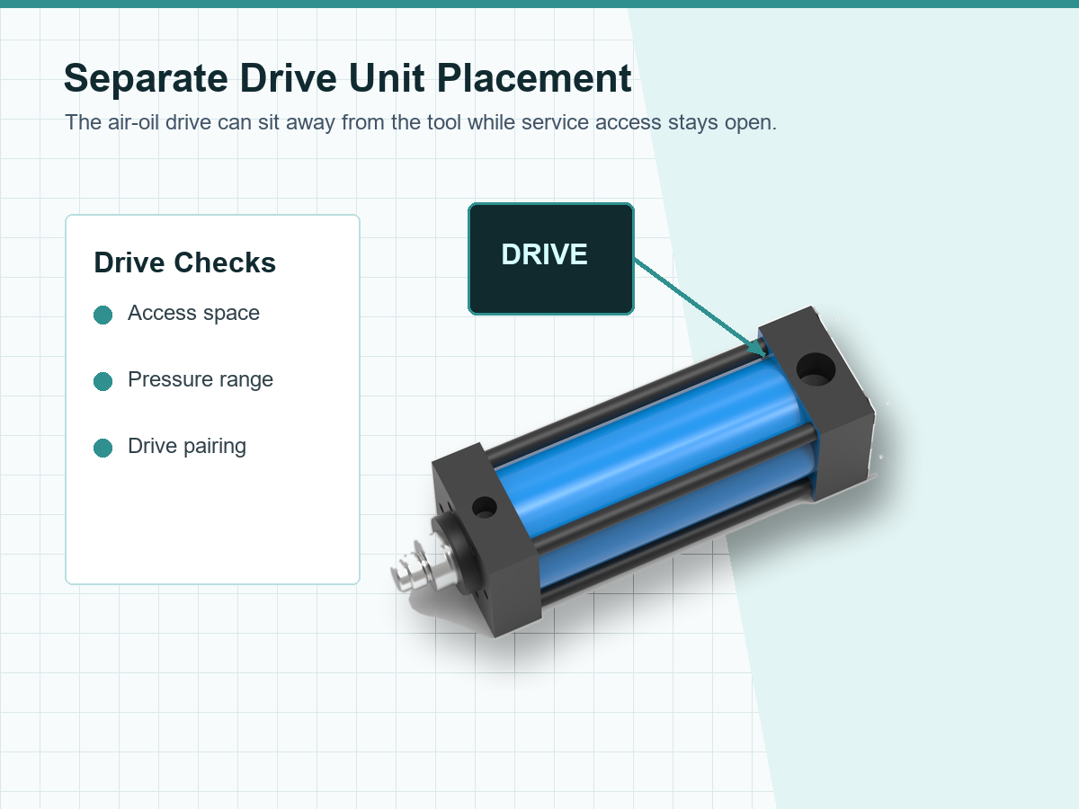
Drive unit
Select the MPS or HMPS family and size it for oil volume, boost volume, cycle, and operating point.
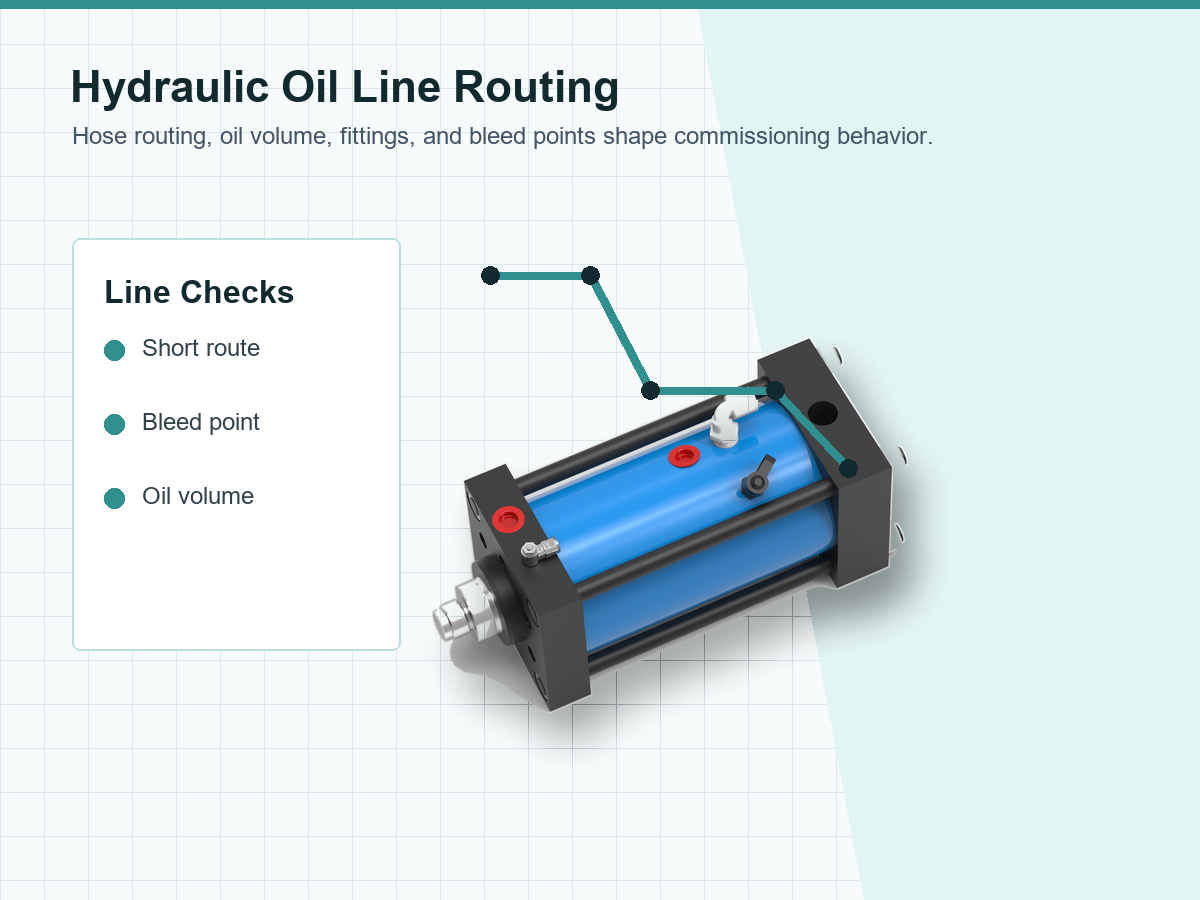
Hydraulic line
Match port and hose size, route length, pressure rating, fittings, protection, fill, and bleed access.
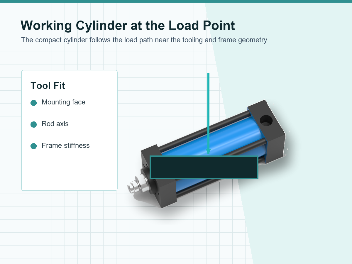
Working cylinder
Shortlist AT or HZ by nominal force, pressure basis, stroke, mounting, dimensions, and return load.
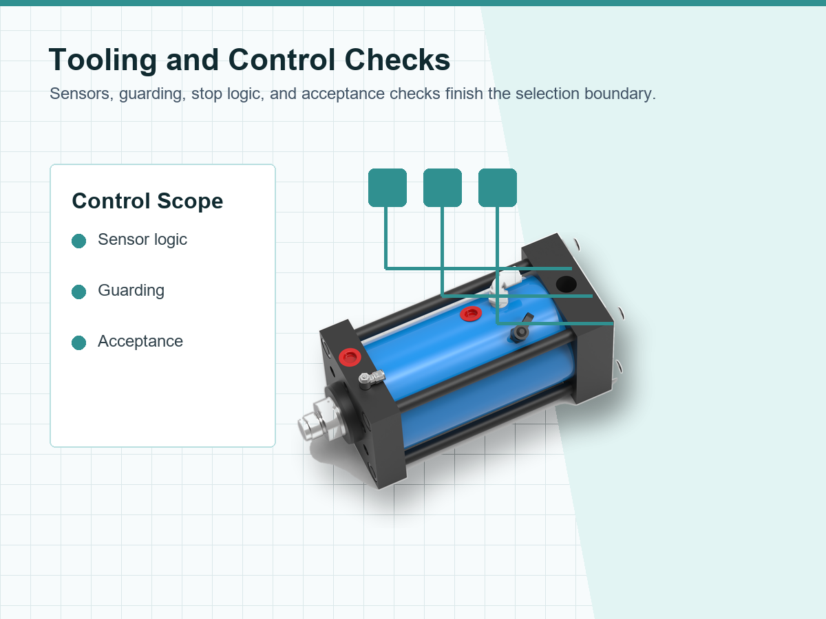
Tool and controls
Verify alignment, frame stiffness, sensing, sequence, safe stopping, guarding, and workpiece acceptance.
Secondary checks: confirm seal compatibility, approach speed, expected reliability, accessory scope, bore size, and every control function.
Terminology buyers may encounter
Search results may call related architectures an air over oil cylinder, pneumatic hydraulic cylinder, or hydropneumatic cylinder. This page uses Simitch’s product-family names and verified pressure points so similar wording does not erase a real configuration difference.
What the catalog can establish
- Model-family force points at a stated cylinder pressure
- Reference bore or dimensional data where supplied
- Oil-volume and hose guidance tied to the source tables
- A starting match between AT and MPS or HZ and HMPS
What the completed machine must establish
- Pressure available under the real cycle and load
- Force delivered at the workpiece and its repeatability
- Frame, tooling, alignment, and side-load behavior
- Control, safety, commissioning, and maintenance acceptance
“Treat the pressure point, usable oil volume, working stroke, hose route, and load path as one selection problem. A model number chosen from force alone is only a partial answer.”
Choose AT or HZ with Verified Pressure and Force Data
AT and HZ are Simitch working-cylinder families for a split system, not interchangeable labels. Compare their source pressure, force range, model count, bore data, drive pairing, and quotation alerts before narrowing the model list.
Get Instant QuoteAT_SERIES // HIGH FORCE
HZ_SERIES // STD FORCE
AT versus HZ family comparison
| Decision point | AT Series | HZ Series | Quotation action |
|---|---|---|---|
| Listed working force | 13-1030 kN | 48-492 kN | Shortlist by process force and margin, then verify installed output. |
| Force-table pressure | 400 bar | 250 bar | Keep the pressure beside every force value; do not compare force without it. |
| Listed model count | 9 | 6 | Select the closest suitable range, not automatically the largest model. |
| Source bore data | Reference mounting dimensions supplied | 50-160 mm bores plus reference dimensions | Use the final approved drawing for machine release. |
| Drive-family starting point | MPS, 69:1 note | HMPS, 39:1 note | Size the drive by oil demand, stroke, cycle, ports, and operating pressure. |
| Visible data alert | AT04 is labeled AS04 in one performance row | HZ table uses 250 bar; HMPS note states 230 bar at 6 bar air | Confirm the exact commercial code and operating point on the quotation. |
Catalog force is a pressure-based reference, not a workpiece guarantee
- Actual pressure at the cylinder can differ from the nominal source point.
- Friction, opposing pressure, fittings, hose behavior, alignment, and tooling affect the installed result.
- A narrow force window may require load sensing, position sensing, pressure monitoring, or machine-level validation.
The honest version of the split-layout decision
The honest version is a trade-off: a modular layout moves the drive away from the tool, but it does not remove circuit and machine responsibilities. Simitch will not claim that nominal cylinder force guarantees installed workpiece output.
Split-Type Pneumohydraulic Cylinder | 15 AT & HZ Models
AT Series – 13 to 1030 kN at 400 bar
Nine AT models cover a wide range at 400 bar. Choosing from peak kN alone creates an installed-force risk, so oil demand and return behavior stay visible.
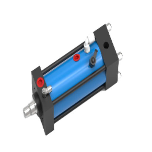
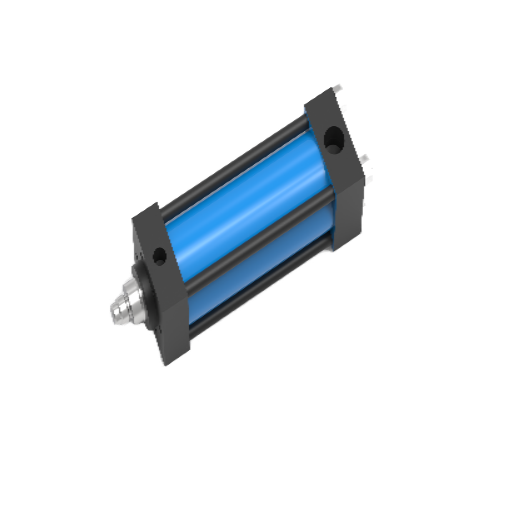
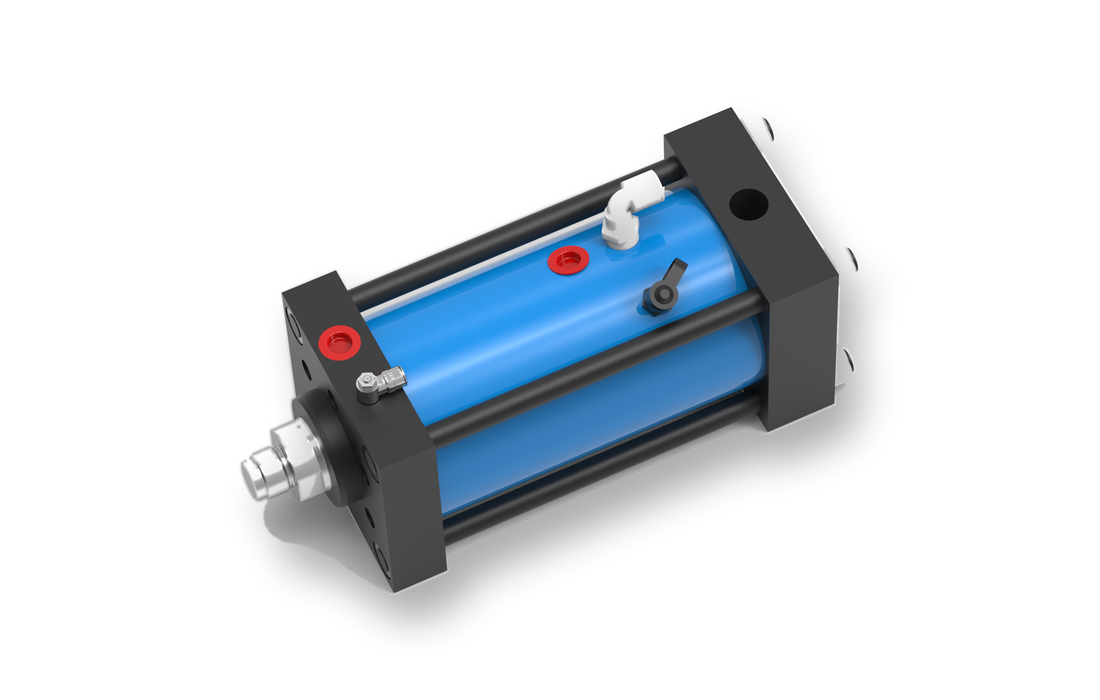
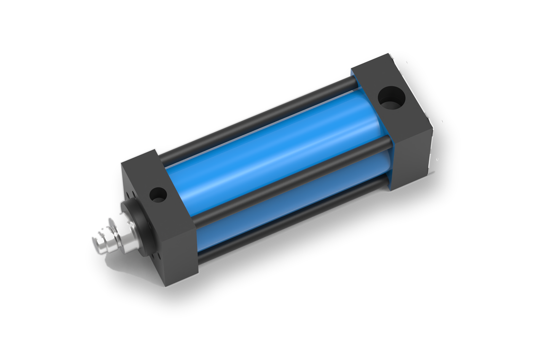
Simitch compact AT04 split-type pneumohydraulic working cylinder
AT04 product rendering. Confirm the AT04 or AS04 commercial code during quotation.
AT selection facts
- Nominal pressing force is stated at 400 bar.
- MPS is the supplied starting drive family.
- Its MPS note states a 69:1 boost ratio and 6 bar air to 400 bar oil.
- Reference dimensions below use a 100 mm stroke basis.
- Dimension B changes with stroke; use the approved drawing for release.
AT Series performance and oil-line reference
AT reference dimensions for 100 mm stroke
Source data includes more mounting, fastener, and port dimensions. These planning values do not replace the final Simitch drawing.
HZ Series – 48 to 492 kN at 250 bar
Six HZ models run from 50 to 160 mm bore. A 250 versus 230 bar mismatch creates a selection risk until the HMPS operating point is confirmed.
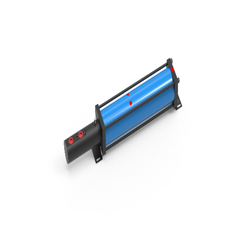
Simitch HZ series split-type pneumohydraulic working cylinder
HZ series working-cylinder rendering. The drive unit is selected separately.
HZ selection facts
- Nominal pressing force is stated at 250 bar.
- Supplied bores range from 50 to 160 mm.
- HMPS is the source starting drive family.
- Its HMPS note states a 39:1 ratio and 6 bar air to 230 bar oil.
- Do not infer HZ installed force from the HMPS note without confirmation.
HZ Series performance and oil-line reference
HZ reference dimensions for 100 mm stroke
HZ and HMPS pressure points require a quote-stage check
- HZ performance data states force at 250 bar.
- An HMPS note states 39:1 and 230 bar oil from 6 bar air.
- A separate HMPS header references 10 bar input and 400 bar output.
- Confirm the selected HMPS variant, approved air pressure, oil pressure, and resulting force in writing.
Match AT to MPS and HZ to HMPS
A mismatch between 230 and 250 bar can make force assumptions wrong. Drive selection must combine oil volumes, ports, line route, stroke, cycle, and the confirmed operating point.
Configuration Rules
AT + MPS starting rule
- Source ratio: 69:1
- Source note: 6 bar air to 400 bar oil
- Six supplied sizes span 470-10,000 cc low-pressure oil volume
- High-pressure boost volumes range from 30 to 390 cc
Simitch HMPS air-oil drive unit
For HZ series working cylinders.
HMPS drive-unit rendering. Working cylinder and oil line are separate system elements.
MPS and HMPS drive-unit planning data
| Drive family | Model | Low-pressure oil (6 bar) | Boost-state volume | Pneumatic port | Hydraulic port | Pressure note |
|---|---|---|---|---|---|---|
| MPS | MPS100.60.30 | 470 cc | 30 cc | G1/2 | G3/4 | 400 bar from 6 bar air |
| MPS | MPS125.60.50 | 790 cc | 50 cc | G1/2 | G3/4 | 400 bar from 6 bar air |
| MPS | MPS160.60.100 | 1800 cc | 100 cc | G3/4 | G3/4 | 400 bar from 6 bar air |
| MPS | MPS200.60.180 | 2800 cc | 180 cc | G1 | G3/4 | 400 bar from 6 bar air |
| MPS | MPS250.60.265 | 6600 cc | 265 cc | G1 | G1 | 400 bar from 6 bar air |
| MPS | MPS300.60.390 | 10,000 cc | 390 cc | G1 | G1-1/4 | 400 bar from 6 bar air |
| HMPS | HMPS100.100.50 | 470 cc | 110 cc | G1/2 | G3/4 | 230 bar at 6 bar per note |
| HMPS | HMPS125.100.78 | 790 cc | 135 cc | G1/2 | G3/4 | 230 bar at 6 bar per note |
| HMPS | HMPS160.100.134 | 1800 cc | 175 cc | G3/4 | G3/4 | 230 bar at 6 bar per note |
| HMPS | HMPS200.100.284 | 2800 cc | 284 cc | G1 | G3/4 | 230 bar at 6 bar per note |
| HMPS | HMPS250.100.395 | 6600 cc | 272 cc | G1 | G1 | 230 bar at 6 bar per note |
| HMPS | HMPS300.100.650 | 10,000 cc | 340 cc | G1 | G1-1/4 | 230 bar at 6 bar per note |
System Planning Checklist
Confirm oil demand
total movement plus the high-pressure working phase.
Check ports and hose
size, rating, route, bend radius, protection, and service access.
Plan fill and bleed
identify high points, reservoir arrangement, and commissioning access.
Define the cycle
approach, contact, press, dwell, return, and restart conditions.
Oil-volume figures create a first screen, not an automatic pairing. Suitability still depends on cylinder stroke, retained oil, hose length, fittings, boost stroke, cycle, and reserve.
Match Force, Stroke, and Process Before Selecting a Model
A useful shortlist begins with the process rather than the catalog table. Required workpiece force, high-force travel, approach travel, duty, load path, available air, and acceptance method reveal whether a split hydropneumatic system fits and which family deserves detailed sizing.
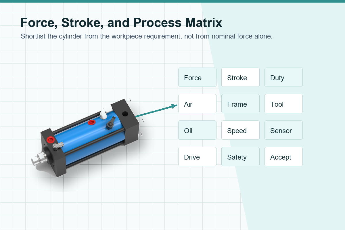
Process-Fit Matrix
Strong candidate
High force over a short working stroke
How much approach, contact, and power travel is required?
Calculate force & oil volume, then shortlist AT or HZ.
Possible w/ controls
Narrow force window at the workpiece
Is catalog pressure enough, or is direct feedback required?
Define sensing, control response, and acceptance.
Depends on tooling
Off-axis or guided load
Which structure guides load & protects cylinder from side force?
Provide frame, guide, and tooling drawings for review.
Architecture review
Long travel at full force
Would a hydraulic or servo press suit the energy demand better?
Compare alternatives before locking the family.
Layout advantage
Restricted tooling envelope
Can the drive and hose be placed safely with good service access?
Share the station layout and oil-line route.
Duty study required
High cycle rate or heat concern
What are the approach, press, dwell, return, and idle times?
Supply a timed cycle and operating-hour profile.
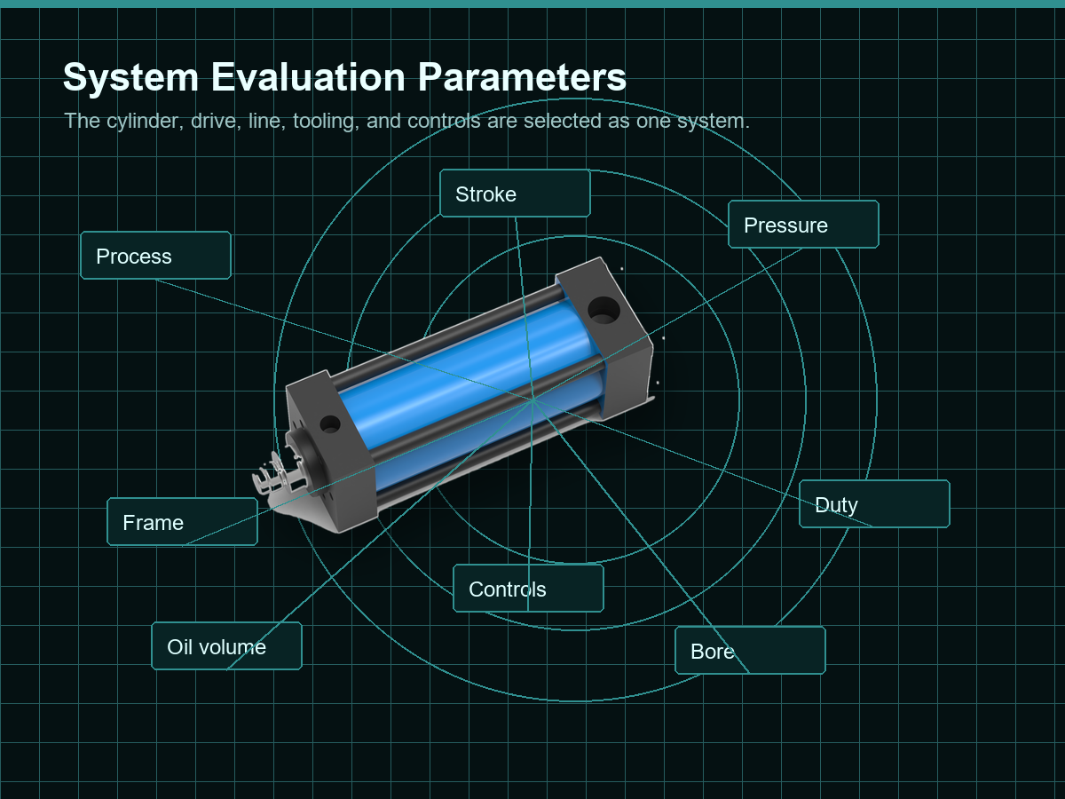
System Evaluation Parameters
8 crucial dimensions that define the mechanical, operational, and safety boundaries for hydropneumatic split systems.
Process
Material, operation, geometry, tolerance, and acceptable part condition.
Travel
Total stroke, working stroke, approach distance, adjustment, and return.
Mechanics
Mounting, frame stiffness, alignment, guiding, tooling mass, and side load.
Controls
PLC sequence, sensors, pressure or force feedback, faults, and restart rules.
Force
Calculated load, margin, contact behavior, and whether force is monitored.
Duty
Cycles per minute, dwell, shifts, annual volume, and changeover pattern.
Utilities
Air pressure at the machine, flow, quality, isolation, and service conditions.
Safety
Risk assessment, guarding, safe stopping, energy isolation, and validation scope.
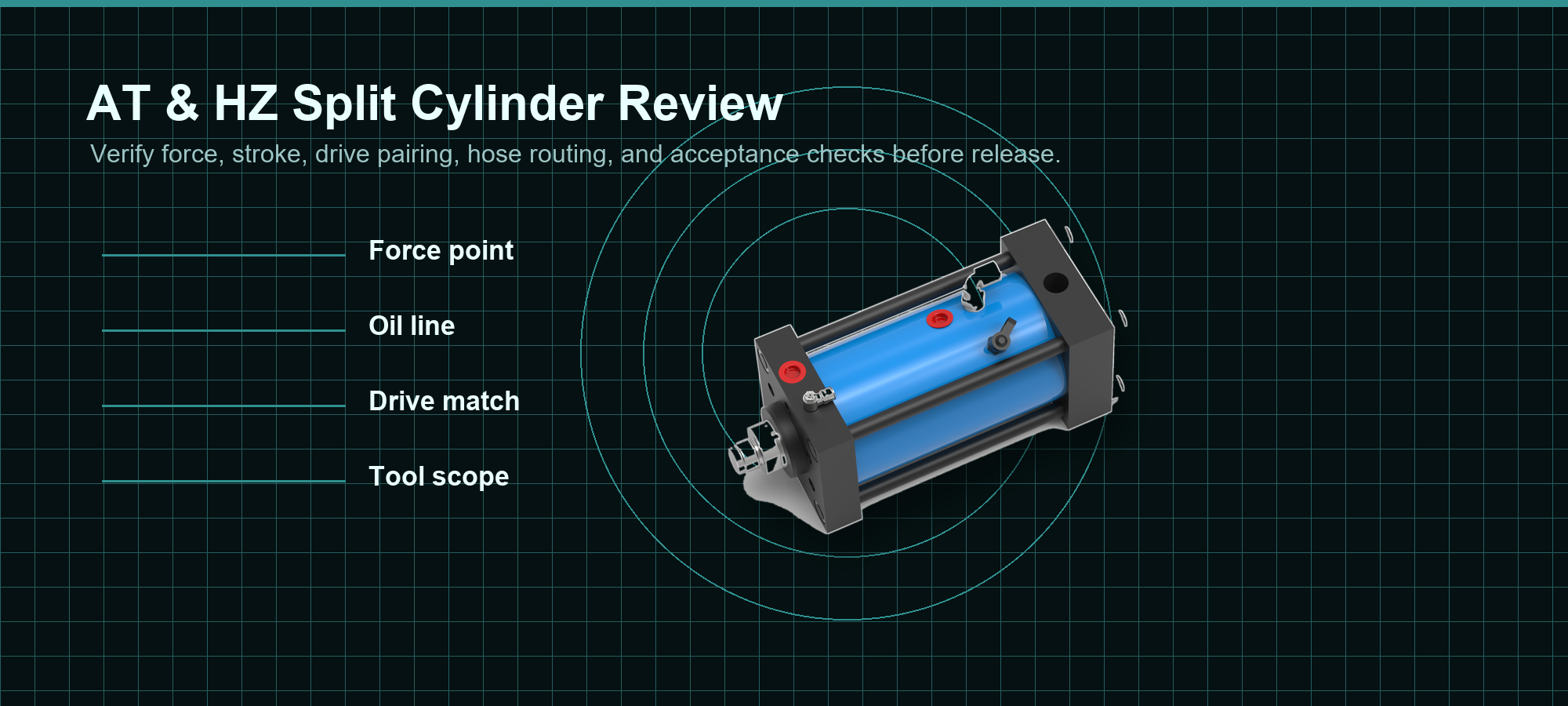
Performance & Cost Review
Evidence-bounded: Compare the proposed system against your alternative using the same production assumptions.
Installed scope
Cylinder, drive, hose, fittings, valves, sensors, controls, guarding, tooling, and commissioning.
Operating inputs
Air demand, cycle time, duty, planned maintenance, leakage checks, and spares.
Quality inputs
Monitoring needs, reject handling, changeover, and acceptance testing.
Commercial inputs
Configured model, stroke, documentation, delivery scope, and support expectations.
AT & HZ Series Engineering Resources
AT & HZ Nominal-Force Model Selector
Enter a process-force target and selection margin to find the smallest listed model whose catalog force meets the resulting nominal-force threshold.
AT & HZ Three-Model Comparison
Compare three catalog rows across pressure, force, oil, hose, and reference-dimension fields before requesting drawings and a configured quotation.
03
6-Input Split-System RFQ Builder
Build a copyable engineering brief that separates confirmed application conditions from open questions, giving Simitch enough context to review the working-cylinder family, nominal-force point, stroke, drive starting point, layout boundary, controls, safety scope, and quotation inclusions.
Build RFQ
FAQ
ISO 4413 Scope
Selection and Integration FAQs
These answers keep catalog facts separate from machine-level outcomes. Two questions reflect recurring engineering-forum problems: air trapped in the oil circuit and controlling actual pressing force rather than reading pressure alone.
What is a split-type pneumohydraulic cylinder system?
It connects a separate air-oil drive to the tool-side working cylinder through a hydraulic line. Remote drive placement can improve packaging and service access.
How do I choose between the AT and HZ Series?
Begin with required workpiece force, high-force stroke, available air, duty, mounting, and control needs. AT lists nine models from 13 to 1030 kN at 400 bar and starts with MPS. HZ lists six models from 48 to 492 kN at 250 bar and starts with HMPS, but its 250 bar table must be reconciled with the 230 bar HMPS note before selection.
Does the listed cylinder force equal the force on my part?
No. Catalog values tie cylinder force to a stated hydraulic pressure, while the part experiences the completed machine. Pressure under load, friction, opposing pressure, fittings, hose behavior, alignment, tooling, frame deflection, contact dynamics, and the measurement method can all affect the result. A narrow force window may therefore need direct force or position feedback, defined limits, and acceptance trials.
Why can a new air-oil press become difficult to bleed?
Air can remain at circuit high points or enter through an incomplete fill, reservoir, or leakage path. Plan the route, fill volume, bleed points, cleanliness, and commissioning checks before assembly. Troubleshooting should follow the approved circuit and service instructions because stored pressure and unexpected motion create hazards.
Can pressure regulation alone control the exact pressing force?
Pressure helps establish theoretical cylinder force, but it does not automatically control the value applied to the part. Friction, opposing pressure, contact dynamics, frame movement, valve response, and tooling can change the measured outcome. If a process has a narrow window, define the sensor location, load cell or pressure feedback, position reference, control response, dwell logic, and sample-acceptance method.
How much stroke can the AT or HZ working cylinder use?
Reference dimensions use a 100 mm stroke basis, and HZ dimension B includes a stroke formula. Send the full travel breakdown for drawing confirmation.
Is the MPS or HMPS drive included with the working cylinder?
Not unless the written quotation says so. It should name the cylinder, drive, hose, fittings, controls, tests, and exclusions.
How is the drive-unit size selected?
Check low-pressure oil volume for movement and boost-state oil volume for the working phase, then add the circuit requirement and agreed reserve. Cylinder stroke, retained oil, hose length, ports, cycle rate, air conditions, dwell, and pressure point influence the result. Simitch should confirm the model against the full timed cycle.
Which applications suit the split system best?
It suits review when high force is concentrated in a shorter working stroke and tool-side space is limited. Part geometry, force curve, cycle, and quality method still decide suitability.
What information is required for a firm quotation?
Provide process and material, required workpiece force, force margin, approach and working stroke, dwell, return, cycles per minute, operating hours, air pressure, layout, mounting, line route, sensors, sequence, guarding, isolation, and acceptance criteria. Add part, tooling, and station drawings where available. Clearly mark unknown values so the quotation separates confirmed conditions from engineering questions.